


400-6188-665
Telephone:0580-8595116
Mobile phone:8613957231625/8618953206839
Fax:0580-8595115
Zip code:316031
Email:info@zsxtjx.com
Address:No. 10 Donghou Rd, Jintang Town, Zhoushan, Zhejiang China
Website:www.zsxtjx.com
Timothy W. Womer TWWomer & Associates, LLC, Edinburg, PA 16116, USA
In 1868, John Wesley Hyatt invented a way to make billiard balls by injecting celluloid into a mold, perhaps in response to a request by billiard ball maker Phelan and Collander. By 1872, John and his brother Isaiah Hyatt patented the injection molding machine. This paper will discuss the evolution of the use of barrier / mixing screw technology in the injection molding process for the plasticating (melting and mixing) of polymers from early plunger machines to today’s sophisticated injection molding equipment. Although John and his brother Isaiah Hyatt patented the injection molding machine that was primitive yet it was quite suitable for their purposes. It contained a plunger to inject the plastic into a mold through a heated cylinder.
While this injection molding machine used a plunger to melt the polymers and force the material into molds, feed screws were already being used to process rubber. However we had to wait until 1946, when James Hendry replaced Hyatt’s plunger in the first screw injection molding machine for the revolution that changed the plastics industry. Hendry’s machine used an auger placed inside the cylinder to mix and melt the polymer, before conveying it forward and injecting the polymer into the mold. Almost all today’s injection molding machines use this technique.
Early plunger presses had straight bore cylinders, which were filled with resin (Figure 1).

Figure 1
Since plastics are very good insulators, it took an excessive amount of time to completely melt the resin in the center of the cylinder. There was thus a need to reduce the time needed to melt the resin in preparation for injection into the mold.
The first improvement on the plunger machine was the installation of a “torpedo” in the cylinder (Figure 2) that would fill some of the volume in the cylinder to reduce the amount of resin in the bore of cylinder, reducing the residence time of the resin. With this improvement, the plunger would then force the resin out near to the interior bore of the cylinder so that the amount of resin required to fill the mould could be heated much more quickly, reducing the cycle time of the molding machine.

Figure 2
One of the benefits of the plunger type molding machines was the capability of producing parts which had a “mottling” effect in the end products as shown in Figure 3.
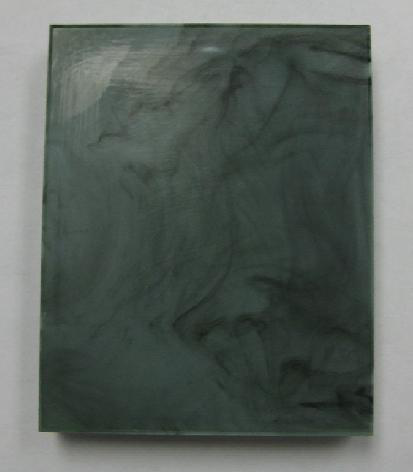
Figure 3
The mottling of parts is easily obtained with a plunger machine and is used to produce interesting looking products such as eyeglass frames, compacts, and fashion accessories. The only downside of this mottling effect is that the pattern is not repeatable and each part is unique.
Similar effects are very difficult to obtain with today’s injection molding machines because screw rotation causes mixing.. As a result some companies still continue to use plunger molding machines to produce parts with this unique mottling effect in the part.
James W. Hendry’s early extrusion machines (Figure 4) used a rotating screw to convey and melt the plastic. The screw conveyed, melted, and pumped the plastic into a plunged or shooting pot which, in turn, filled the mold. This process improved mixing of the processed resins and gave much higher production rates.
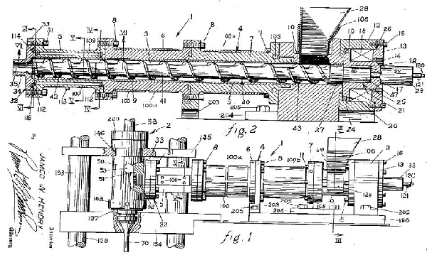
Figure 4
The next step was the reciprocating screw, generally regarded as having been developed in the U.S., William Willert at Egan Machinery in 1952 and patented in 1956 (Figure 5).

Figure 5
Some credit Hans Beck of BAST in Germany with inventing the first reciprocating-screw machine in 1943. He also filed for a patent but reciprocating-screw molding machines were not commercialized in Europe or the U.S. until a decade later.
The reason for going through the history of injection molding is to understand the common nomenclature that is used in describing the various parts of the screw itself (Figure 6)
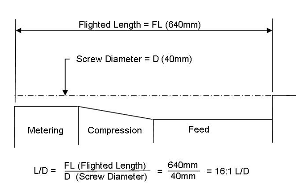
Figure 6
As shown in Figure 6, the L/D ratio of a screw is the flighted length divided by the nominal screw diameter, so for example, on a 40mm screw, if the flighted length was 640mm long then the screw L/D would have been a 16:1 L/D screw.
Almost all early injection machines had only 16:1 L/D injection units installed on them. Also, most of the early injection units on these machines had a 4:1 L/D injection stroke or reciprocation for filling the mold. As shown in Figure 7, the feed section is effectively shortened by the reciprocation screw as it accumulate enough molten polymer to fill the mold, In the example of a 16:1 L/D screw, if a full shot of 4 L/D is required then the actual plasticating length of the screw is only 12:1 L/D.
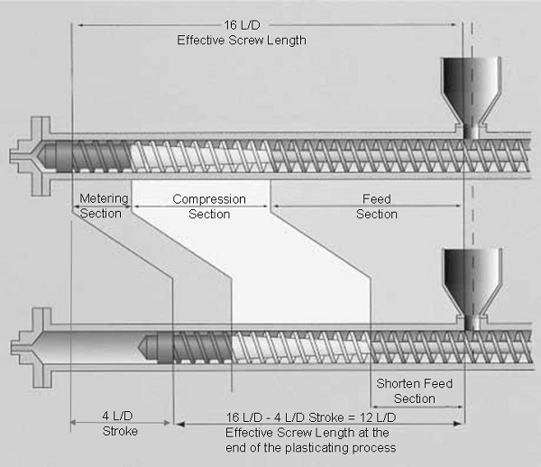
Figure 7
As engineers began to understand how the reciprocation stroke of the injection unit affected the performance of the early injection screws, they resolved the problem associated with conveying solids by using screw design technology that had been developed for extrusion screws.
They maintained the same proportions that were being used in many early general purpose extrusion screws (33% in the feed section, 33% in the compression section, and 33% in the metering section of the screw). Thus, after allowing the four diameters of the screw for the reciprocating action of the screw, they divided the 16:1 L/D injection screws into 4 L/D in the feed for stroke, 4 L/D for solids conveying of the pellets, 4 L/D of compression for the melting of the polymer and finally 4 L/D in the metering for finishing the melting process and pumping as shown in Figure 8.
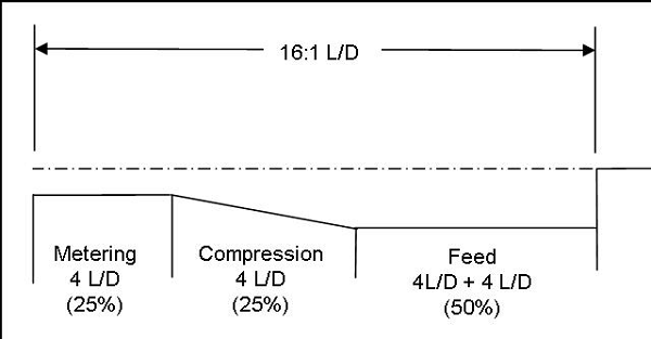
Figure 8
This configuration became known as 50/25/25 geometry, which stood for the percentage of the overall flighted section for each section of the screw.
The next term that is commonly used to describe a screw design is its compression ratio (CR). The the compression ratio (CR) of a three zone screw is defined as the depth of feed section (feed depth, mf) divided by the depth of the metering section (metering depth, mm) as indicated in the equation below:

Thus a screw which would have a feed depth of .300” and a metering depth of .100” would have 3:1 Compression ratio.
 (Example 1)
For many years, injection molding processors described their screws using only the L/D and the compression ratio. Thus a typical screw might be described as a ‘General Purpose 50/25/25 screw with a 3:1 compression ratio’. As explained below this would result in variability since one Original Equipment Manufacturer (OEM) or screw manufacture would not use the same depths as another OEM or screw manufacturer.
If a screw is described only by its compression ratio, the depth of the screw flights can still vary. A screw of the same diameter with a 3:1 compression ratio could have totally different depths in the metering and feed sections. For example:
 (Example 2)
Examples 1 and 2 describe common section depths used on 65mm screws which have totally different processing capacities. The screw for Example 1 would have a lesser recovery rate, in other words, it would require a longer time to accumulate the needed polymer to fill the mold and a much higher channel shear rate than the screw of Example 2
The depths in Example 1 would be suitable for a low viscosity engineering resin such as Nylon, PET, or PEEK. Resins such at PE or PP could also be processed with this screw but at a much reduced recovery rate.
A screw with the depths shown in Example 2, would be more typical for a PE or PP resin, but would not process the engineering resin very well at all.
For nearly two decades (1950-1970), the injection molding industry mostly used the reciprocating screw as the only a means of conveying the resin forward and forcing it into the mold.
During these years problems were frequently encountered with color uniformity, when color concentrate was being added to virgin resin. If color uniformity was critical, pre-colored resins were often used. An alternative was to improve mixing by increasing the back pressure on the injection unit so to increase the residence time in the screw and allow the screw to work the master-batch enough to improve the color dispersion.
The down-side of using increased backpressure for improving mixing was that it would always increase the plasticating time, and very often increases the melt temperature of the resin. Both of these elements would increase the overall cycle time of the total injection molding process.
As the need to improve production rates became necessary as the growing injection molding industry was rapidly growing in throughout the world, new and ingenious plasticating technology was developed starting in the late 1960s and early 1970s.
These new developments will be covered in the Part 2 of this article. Stay tuned ......
Plastics Technology, October 2005, “No. 1- Reciprocating-Screw Injection”
US Patent 2,705,342 – Hendry Apr 5, 1955
US Patent 2734226 – Willert Feb 14, 1956
Kunststoffe, Vol. 92 (2002), “Plasticising in Critical Areas-Exhausting the Potential of the Single Screw”
Timothy W. Womer, CPlasT
